STEERING WHEEL DISASSEMBLY
Tilt-Steering: Loose
[From: http://buickperformance.com/tiltsteeringcolumnwobble.htm ]
 |
With the lock plate and the turn signal disc removed, you can see the turn signal mechanism. The 3 arrows starting at 1 o'clock and going clockwise hold the turn signal assembly to the steering column upper section. The last screw holds the turn signal arm to the assembly. The turn signal screw has slightly different threads than the other three so don't get them mixed. Don't forget to remove the hazard flasher knob.
|
 |
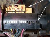
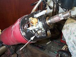
With the turn signal assembly removed, you will see the three large Phillips screws to be removed so the upper steering column collar can be removed from the column. The white single arrow indicates the key cylinder tang that needs to be depressed in order to slide the key cylinder from the column. On some of the 69-72 versions the tab can be covered by flashing and you will need to use a small screwdriver to break the flashing to access the tang. The black arrow indicates the turn signal contacts and can be removed after the key cylinder. It is an easy piece to break so take you time to remove it along with the small black spring that holds it in place.
|
 |
Arrow indicates the "pop-up" spring for the tilt mechanism. Use a Phillips screwdriver to press down and rotate the cap counterclockwise to remove. Gently ease up on cap slowly so spring does not fly out.
|
 |
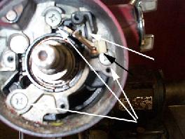
Now you will need to disassemble the lock cylinder interface. The lower arrow indicates the 1/4" hex head screw holding the lock plate pin spring. The upper arrow shows the snap ring that needs to be removed from the gear that engages the rack below. The second arrow from the left shows the tilt lever guide plate and needs to be removed. It easily slides out. The arrow on the far left, is the pivot pin. More info on this below.
|
 |
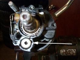
Here is the same side view but a different angle. Arrow indicates screw that needs to be removed. Notice the steering wheel nut threads in this pic. These are 9/16-18 threads.
|
 |
With gear, spring and lock pin removed, you will need to remove the pivot pins.
|
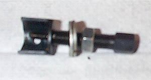 |
This is the pivot pin removal tool for Saginaw columns. This is a must to remove the pins. Can be purchased from auto tool stores as well as www.harborfreight.com
|
 |
Simply screw tool into pivot pin and then tighten large 1/2" nut. As you can see in the pic, the pin is about 1/4" out. Repeat for the other side.
|
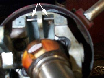 |
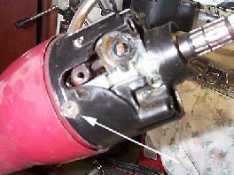
Arrows indicate the bars that tilt collar engages. Use the tilt lever and pull it forward. Lift the collar as you pull on the tilt lever and the column section will unhook from these bars.
|
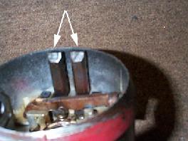 |
These are the two levers that hold onto the pins.
|
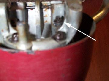 |
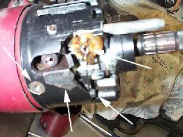
AHA!!!!!! This is the problem. Notice how this screw is about 1/8" up from the base pivot material. There are four total and you can only see three in this pic. The fourth is also about 1/8" up and needs to be tightened. To permanently fix this problem clean the threads and then apply some Loc-tite thread locker. Tighten all four screws using an E8 Torx socket.
|
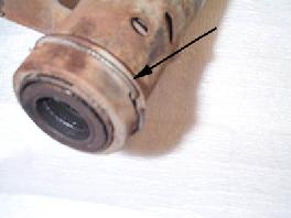 |
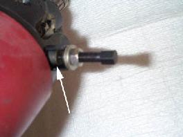
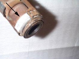
This is the engine side of the column. Remove the retaining ring indicated by the arrow to remove retaining collar so you can access the lower bearing.
|
 |
Use a small screwdriver to gently tap down the direction of the arrow to remove the bearing.
|
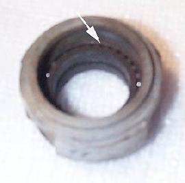 |
Bearing is removed from the column. Hard to notice in this pic but the bearings are "bone dry" and need to be greased. Use a grease needle in a grease gun to pack the bearings.
|
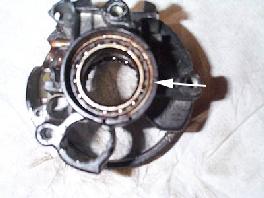 |
This is the upper column section. Notice bearings here are also bone dry. Use the grease needle again.
|
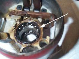 |
Here is the flip side of the same piece. Lower bearings are also dry. Grease them too.
|
www.gnttype.org/techarea/suspension/t_steering.html
Fixing A Loose Tilt Steering Column
An apparently common problem with GM Tilt Steering columns is that they become loose from four bolts backing out deep in the tilt assembly. A good shop will be experienced in taking care of for about $100. With the correct tools and a bit of patience you can fix it yourself.
You Will Need: Special Tools Required:
Steering Wheel Puller $10.00, but a harmonic balancer puller will also work
Don't attempt to pound the wheel off, you could damage the steering column.
Locking Plate Remover $15.00, available from autoparts store.
Pivot Pin Removal Tool GM part J21854-01 (not sure about availability from autoparts store)
Procedure:
1. Remove steering wheel, this would be a good time to disconnect the battery as well.
2. Pry off plastic cover
3. Remove lock plate. With the tool this is easy. The tool compresses the lock plate against it's spring so that you can get the retaining ring off. It is possible to take this off with C-Clamps, Large Channel locks, etc. Can be very difficult to put back together with these tools. (I did it both without and with the tool, trust me it is $15 well spent)
4. Remove philips screw that holds small piece of metal that connects to turn signal stalk.
5. Remove 3 screws that hold turn signal switch assembly in place.
6. Unhook wiring harness to turn signals. This is located under the dash attached to the base of the steering column.
7. Next you will need to loosen the mounting bracket that holds the steering column to the dash and then remove at least two of the bolts that hold the bracket to the column so that you can thread the wiring harness up to allow the housing to be removed latter.
8. You will see a switch with two long copper pieces coming over the top of the ignition lock. Put the key in and turn to the on position. Pull the switch out with a pair of pliers. A small clip should also come out. Note the way all of this is oriented so that you can put it back later.
9. Remove small torx screw to release lock cylinder, pull the lock out.
10. Remove three large torx bolts (#30 I believe)
11. At this point you are ready to pull the housing off. As you pull it out a small plastic piece will fall out on the left (driver's) side. This is for the dimmer switch.
12. Also some of the parts for the upper bearing will come out. Note the orientation for later assembly.
13. Below the shaft you will see a retainer for a large spring that is inside the tilt assembly. (About 1/2" in diameter with a large square hole) Use a large screwdriver to depress this enough to turn 1/4 turn counter clockwise. Remove spring assembly.
14. Now you are ready to pull the pivot pins out. There are two of them going in the sides at about the 3:00 and 9:00 positions. They are about 3/8" in diameter and have a small hole threaded in the middle (#10-32 I believe) I managed to break off a bolt in one of these which required that I pull the entire steering column out to get the bolt drilled out so be careful. The GM tool looks like this:
| |
| |<-----------threaded rod
| | |="===|" <------- nut
____________ | | | |<------ semi circle housing | ||
| | || | || ||<--------threads into pivot pin
To use this you thread it into the pivot pin. Make sure that the housing is solidly against the column, not interfering with the pivot pin. Tighten the nut down while holding the threaded rod still to pull the pivot pin out.
The tool that I first tried to make was similar to the above using a bolt and a socket. I do not know what went wrong exactly but I broke the bolt off inside the pivot pin. The guy that drilled out the bolt said that you can pull the pins by threading a bolt in and prying up with a pair of pliers. For what it is worth the guy I borrowed the GM tool from said that sometimes that tool breaks as well.
15. Pull the tilt adjust arm back and tilt the column up as far as it will go.
16. Examine the mechanism that is used to activate the ignition switch. Study all of the carefully because if the next step doesn't go just right you will need to reassemble this.
17. Tilt column housing up and then to the right. What you are trying to do by rotating to the right is to get the rod that come up from the ignition switch (located on the side of the column) to the actuator rack that move back and forth when the key is turned.
18. Pull the housing off. If you were successful in getting the switch to release from the rod above great! If not you will need to reassemble the switch mechanism - No big deal There is a metal spring clip about 3/4" long that applies pressure to the piece that slides back and forth. It goes in with the flatter part at the top. Turn the gear as far clockwise as possible. Thread the actuator rack in from the bottom until it engages the gear.
19. Now you can see the four bolts that you are after! They look like torx bits. I was able to get on them using a 6 point 1/4" socket. Someone else had said that they used a 5/16" 12 point although I believe that they must have meant 3/16".
20. Reassembly is pretty much the reverse of the disassembly process. A few tips:
To get tilt hosing back on pull back on tilt lever to release the locking shoes. Place over the shaft and tilt to the left to try to engage the rod to the ignition switch. Then pivot downward until holes line up for the pivot pins. Verify that the switch is working. Don't forget that the transmission has to be in park to have the full range of motion.
Drive the pivot pins in with a hammer.
The plastic piece for the headlight dimmer pushes down on a rod. Only one way it will fit.
That's it. As you may be able to tell I had a terrible time with this. I am pretty sure that I could do it all again pretty quickly now that I know how everything fits together.
---------------------------